Disc Brake Installation
PART # 0149DB DISC BRAKE KIT INSTALLATION WITH THE
TIEDOWN MODEL 66 - 6600# DISC BRAKE COUPLER
|
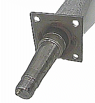
[ 1 ] To begin the installation, it requires that your axle be compatible with the components of the brake kit. This first requires that your axle spindles use bearing # 68149 (1 3/8") inner bearing next to the seal and bearing number # 44649 (1 1/16") outer bearing next to the spindle nut. Your axle must also have a 4 on 4 hole brake flange in place. If your axle has these features you can proceed with the installation. If it does not, you will need to purchase an axle to match these system requirements. [See pages 2 and 3 of the CHAMPION TRAILERS PARTS CATALOG, For axle order information. With a spring suspension system, when only one brake axle is being installed on a tandem axle trailer, it is advisable to have brakes on the rear axle for maximum system performance. Rotational torque applied to axles during braking shifts the equalizer of a spring suspension system and applies more weight to the rear axle allowing the rear tires to dig into the road. If brakes are installed on the front axle, the wheels may skid during braking. [ 2 ] BRAKE COUPLER INSTALLATION The Part # 0149DB disc brake kit is supplied with a Tiedown Model 66DB [ 6600#] max. cap. disc brake coupler , and a reversing solenoid valve. Note: this coupler is designed for use with disc brakes and must not be used with drum brakes! Disc brakes provide 100% braking in both forward and reverse directions, whereas drum brakes lose most of their braking ability when backing up. Therefore a method of disabling the trailer disc brakes, during reverse direction operation, is required. This brake kit is supplied with a reversing solenoid valve. This valve is connected to the back up light on the tow vehicle via a plug which is supplied with the kit. When the tow vehicle is put into reverse , the back up light comes on which then activates the reversing solenoid valve , and disables the trailer brakes while backing up . If your existing idler (non-braking coupler) is bolted on and has the standard 3" centerline mounting bolt holes, you should be able to remove the old idler coupler and reinstall the new Tiedown brake coupler with the mounting bolts supplied with this kit. If your old coupler is welded on or has non standard bolt hole placement, you will need to remove the existing coupler and drill new holes.
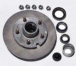
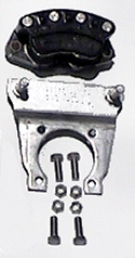
[ 3 ] HUB ROTOR INSTALLATION You should have previously confirmed your axle bearing and brake flange compatibility with the components of this kit. Now you are ready to remove the existing idler hubs from the axle. Be sure to retain the spindle washer and spindle nut for reuse with the disc brake installation. They are not supplied with the brake kit and may have parameters that make them unique to your spindles. At this point pre-pack your bearings and install them and your seals into the hub rotor units. Be sure that you fully pack the bearings before installation, and be sure to use high temp grease. Disc brakes will run hotter than either idler hubs or drum brakes. [ 4 ] PRE-LOADING THE BEARINGS Whether installing idler hubs, drum brakes , or disc brakes it is essential that you pre-load the bearings during hub installation. To properly pre-load your bearings proceed as follows. After pre-packing your bearings with grease and installing the rear bearing and seal into your hub rotor, slide the hub-rotor onto the spindle and install the outer bearing , thrust washer, and spindle nut. Now tighten the spindle nut UNTIL IT BECOMES SNUG and then about a ¼ turn, or about 10 ft. pounds of torque more. Rotate the hub rotor by hand about 10 revolutions. At this point back off of the spindle nut until it is very loose, and re-tighten finger tight while turning the hub in the direction that the nut is turning while tightening. When you feel the snug point again, install the cotter pin, tab washer or other nut retaining device. WARNING - DO NOT OVER-TIGHTEN THE SPINDLE NUT. TO DO SO MAY RESULT IN FAILURE OF THE BEARINGS. [ 5 ] INSTALLING THE CALIPERS The caliper head slides onto the 2 EA. - ½" stainless pins in the galvanized brake flange adapter plate. The caliper head floats on these two stainless pins. Be sure that the caliper slides easily onto these pins , and lubricate the SS pins with grease before assembly . With the caliper on the pins of the adapter plate, slide the caliper onto the top edge of the stainless rotor. This should allow the adapter plate to have it's holes line up with the four holes in the brake flange welded to the 3500# axle. The galvanized adapter plate attaches to the front (spindle) side of the brake flange on the axle. You can now install the 4 ea. 7/16" x 1" stainless bolts to attach the adapter plate to the brake flange. Torque to 25 ft pounds. [ Note ] these installation instructions are intended for the 5 lug - 3500# disc brake units with 4 hole brake flanges . If you are installing 6 lug - 5200# disc brake units , the adapter plate has 3-3/8" holes and it also has a galvanized spacer plate that installs between the adapter plate and the front of the brake flange on the axle. [On the 5200# axles the brake flange has 5 - 3/8" holes . With the Tiedown disc brake units for this axle only the top three holes are used to attach the adapter plate , and spacer. Brake flanges on many axles may not be square with the spindle shaft and may require shimming the galvanized adapter plate to align the caliper head with the rotor. To test for alignment, now that you have the adapter plate securely bolted to the brake flange, rotate the hub/rotor. The hub/rotor should turn with only a moderate amount of dragging between caliper pads and rotor. If the rotor is hard to turn or is locked up and will not turn, the brake flange is probably out of square with the spindle. Visually observe whether the edge of the rotor and the calipers are out of alignment. If brake flange misalignment is evident, loosen one or more of the nuts holding the adapter plate to the brake flange until you can hold the caliper head in a linear relationship to the rotor. Where necessary, install thin 7/16" stainless flat washers between the brake flange and adapter plate .These shim washers are not supplied as part of this kit. If it is necessary to remove the stainless nylon self-locking nuts from the brake flange mounting bolts, you should replace them. Nylon self lock nuts are intended for one use only. The hub/rotor should now turn easily with only moderate pad to rotor drag. The calipers on the 3500# axle are normally positioned nearly vertical at the 12:00 o'clock position, however they will work in any position. The vertical 12:00 o'clock position is best for brake bleeding, giving the best opportunity to totally purge all air from the system. NOTE: Any air trapped in the system will radically decrease braking performance. If installing 6 lug 5200# disc brakes the calipers must mount at the 12:00 o'clock position.
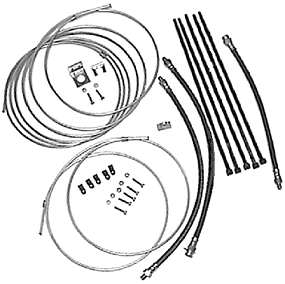
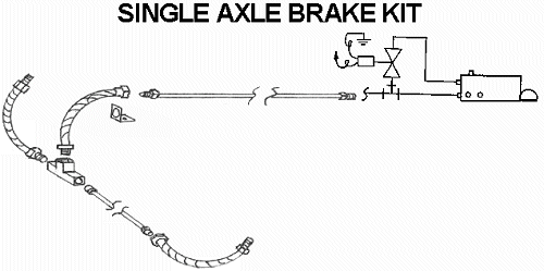
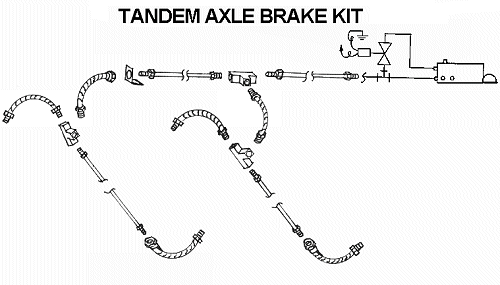
[ 6 ] BRAKE TUBING INSTALLATION The brake tube kit supplied with this disc brake package can be used with either torsion or spring suspension axles. The standard stainless brake line tubing kit includes one each 16' mainline tubing. This tubing is routed from the brake coupler back to the brake axle, down one side of the trailer. If your trailer requires more than Attach the mainline tubing to the female side of the hose and install the brass tee to the male end of the brake hose. This provides a flexible connection from the trailer frame down to the axle. The 18" male/male hose goes from the tee to the near side caliper. The 5' tube goes across the axle and the 18" male/female connects to it and the far side caliper. The brake tubing is now strapped to the axle using the black 14" tyraps included with the kit. Be sure to route the flex hoses so that they are not rubbing against the trailer frame during highway travel .
WARNING: DO NOT CUT THE STAINLESS TUBING. USE FACTORY COMPLETE PIECES ONLY!! US - DOT regulations require double flare on brake line tubing. This cannot be accomplished without special tooling on the stainless tubing. Before bleeding the system, check that all brake line tubing connections are tight. [ 7 ] BLEEDING THE BRAKES The Tie Down Engineering® disc brakes included in this kit have dual pistons with two bleed valves per caliper. It is important to *OPEN ONLY ONE BLEED VALVE AT A TIME* during the brake bleeding process. Begin bleeding the brakes by opening one bleed valve on the caliper closest to the master cylinder in the tubing sequence. On tandem brake axle installations, bleed the brakes on the front axle first. Before attempting to bleed the brakes it will be necessary to pre- bleed the master cylinder. First remove the brake line tubing from the brass tubing adapter at the rear of the master cylinder reversing solenoid. Now hold your finger tightly over the hole in the rear of the brass tubing adapter. After filling the master cylinder reservoir with clean DOT 3 brake fluid, begin pumping the master cylinder. To pump the master cylinder on the Tiedown brake coupler insert a screw driver into the hole on top of the coupler and pull forward and backward . Air bubbles will purge through the holes on the bottom of the master cylinder reservoir as you pump the master cylinder. After several strokes you will feel pressure building up on your finger at the rear of the cylinder. Occasionally while pumping, release pressure and let air escape past your finger. Eventually a fountain of fluid will erupt from the holes in the bottom of the cylinder reservoir. This affirms that the master cylinder Is now primed and ready to bleed the brakes. Reconnect the brake tubing and proceed to bleed the brakes. BE CAREFUL NOT TO LET THE MASTER CYLINDER RESERVOIR RUN DRY DURING THE BLEEDING PROCESS. Every three or four stokes, refill the reservoir. If air is sucked into the master cylinder, you must begin the bleeding process anew. Install a clear plastic hose onto the bleed valve and insert the loose end of the hose into a clear container partially filled with brake fluid to observe air bubbles. It is best to have this fluid receiving container at an elevation above the caliper during the bleeding procedure. For best results during bleeding, pinch the bleed hose, or close the bleed valve on the return stroke. Pump fluid through the system until no bubbles are present. Close the bleed valve on this piston and repeat the process on the second piston. When completed with the first caliper, repeat the process on the next caliper. Brake fluid is toxic. Dispose of the containers and used fluid properly. (NOTICE) Disc brakes require high static line pressure for effective braking performance. Any air trapped in the system will drastically reduce braking performance. Proper brake bleeding is the best way to assure good system performance. [ ALSO ] because disc brakes require high static line pressure for optimum system performance , if you use non steel brake line tubing [ all flexible hose ] for your brake line tubing, you may have lower static system line pressure and this may reduce the overall system braking results . It is strongly recommended that DOT approved steel or stainless steel brake line tubing be used and that flex hoses be kept to a minimum.
[ 8 ] TESTING THE BRAKES Reinstall the tires back onto the hub/rotors and have an associate rotate the wheel rapidly. While this is being done, apply firm, aggressive pressure to the manual pump lever screwdriver , that you used to pump the brakes during the brake bleeding procedure. The wheel should come to an abrupt stop. Now release pressure on the screwdriver and pull the brake coupler to it's fully telescoped [ towing ] position . The wheel should now turn with only a moderate dragging of the pads. THIS COMPLETES THE INSTALLATION OF YOUR DISC BRAKE SYSTEM
Standard DISC BRAKE System TROUBLE SHOOTING
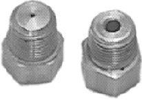
Disc brakes normally run hotter that drum brakes due to partial contact of pad and rotor during normal highway travel; whereas drum brakes have a return spring that retracts the brake shoes with virtually no contact between the shoes and drum. Your disc brakes during normal highway travel should be "very warm", but still allow you to put your hands on the hub without burning. However during frequent braking periods, such as stop and go braking, they may be to hot to touch. NOTE: IF BRAKE HEATING IS EXCESSIVE, CHECK THAT THE HOLE IN THE BRASS BRAKE LINE TUBING ADAPTER IS NOT OBSTRUCTED. Also be sure that the master cylinder tubing adapter orifice is bored to a minimum of .0625" . This will facilitate the return flow of fluid to the master cylinder on the return stroke.
Since disc brakes run hot, it is important to use a high Temperature grease specifically intended for disc brakes. Other greases may lose their viscosity at higher temperatures and liquefy, allowing them to sling out past the seal or dust cap. CHECK FOR WORN SEALS. In most installations it will be necessary to install SPINDLE-LUBE dust caps and bellows plugs, to allow the grease to expand during high temperature operation.
[ 1 ] Air bubbles may be present in the system. SOLUTION: Re-bleed brakes. *Also check fluid level in the master cylinder. [ 2 ] Corroded master cylinder walls not allowing high pressure to build up on the power stroke . SOLUTION: Replace or rebuild master cylinder. [ 3 ] Inadequate number of brake units for the load being towed. SOLUTION: If load being towed is over 3000# gvwr, put brakes on all axles. [ 4 ] If you have an all flex hose brake line tubing installation you may need to change to a steel brake tubing system . As static line pressure increases in flexible tubing it swells up in response to the increase in pressure . This decreases the over all system line pressure and can result in reduced brake system performance , especially when used with disc brake systems , and their higher line pressure requirements .
* Disc brakes give 100% braking either forward or backward. On most disc brake systems, a reversing solenoid valve is installed. * If your reversing solenoid is not operating properly, check for proper ground connection on both trailer and tow vehicle. Also check that at least 10VDC is available at the (+) positive lead going to the solenoid. * To test the electrical operation, have an assistant put the tow vehicle into and out of reverse, confirming that the back up lights on the tow vehicle come on when and only when the tow vehicle is in reverse. You should hear or feel a discernible click as the valve cycles. NOTE: IF THE (WHITE) BACKUP LIGHTS COME ON IN ANY GEAR OTHER THAN REVERSE, THE BRAKES WILL BE DISABLED IN THAT CONDITION!! This could disable the brakes during normal highway travel. * NOTE : the Tiedown disc brake coupler is equipped with an emergency brake lock out pin . You can use it to lock out brakes when backing up , HOWEVER it should only be used as an emergency device . ALWAYS REMOVE THE PIN WHEN TRAVELING FORWARD , OR the BRAKES WILL BE DISABLED!!!!
WARNING: WHEN REPLACING DRUM BRAKES WITH DISC BRAKES , and using your preexisting SURGE BRAKE COUPLER , the brake coupler WILL REQUIRE MODIFICATION . If you are replacing drum brakes with disc brakes on a trailer , and are using your existing surge brake coupler, there are some modifications that will be required of the brake coupler for successful operation with disc brakes. [ A ] First it will be necessary to remove your residual valve in the master cylinder .WARNING: Attempting to puncture the residual valve may damage components internal to the master cylinder. It is only recommended that you remove the residual valve instead of puncturing it!
[ B ] Second the brass tubing adapter at the rear of the master cylinder should have a minimum orifice diameter of .0625" or larger. [ C ] Reversing solenoid valve will normally be required. [ D ] WARNING: IF YOU MANUALLY LOCK OUT THE BRAKE COUPLER , AND FORGET TO REMOVE THE LOCK OUT MECHANISM , YOUR BRAKES WILL BE DISABLED DURING NORMAL FORWARD HIGHWAY TRAVEL !! |
|
PRIVACY POLICY Send website comments to generalsales@championtrailers.com |

